
Circuit to control wind parks via LoRa-WAN.
 Tobias Müller
eec41addab
update Header
Tobias Müller
eec41addab
update Header
|
11 months ago | |
|---|---|---|
| Build | 1 year ago | |
| Documentation | 1 year ago | |
| Library | 1 year ago | |
| Pictures | 11 months ago | |
| Project | 1 year ago | |
| Script | 1 year ago | |
| Source | 1 year ago | |
| Test | 1 year ago | |
| .gitignore | 1 year ago | |
| LICENSE | 1 year ago | |
| README.md | 11 months ago | |
| README.pdf | 11 months ago |
README.md
LoRa-WindPower-Control
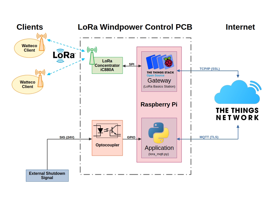
Connection Overview
Pin Assignment
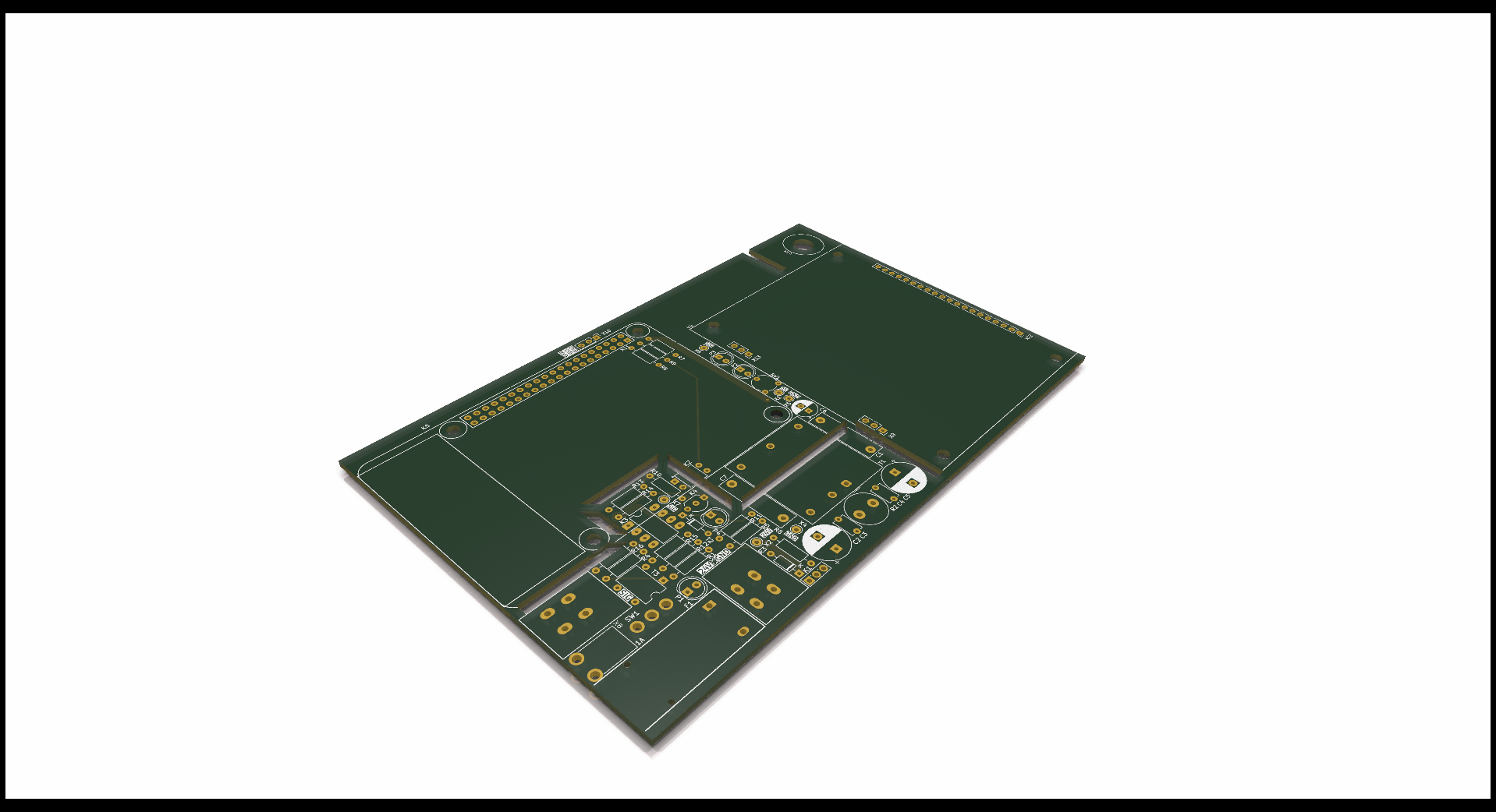
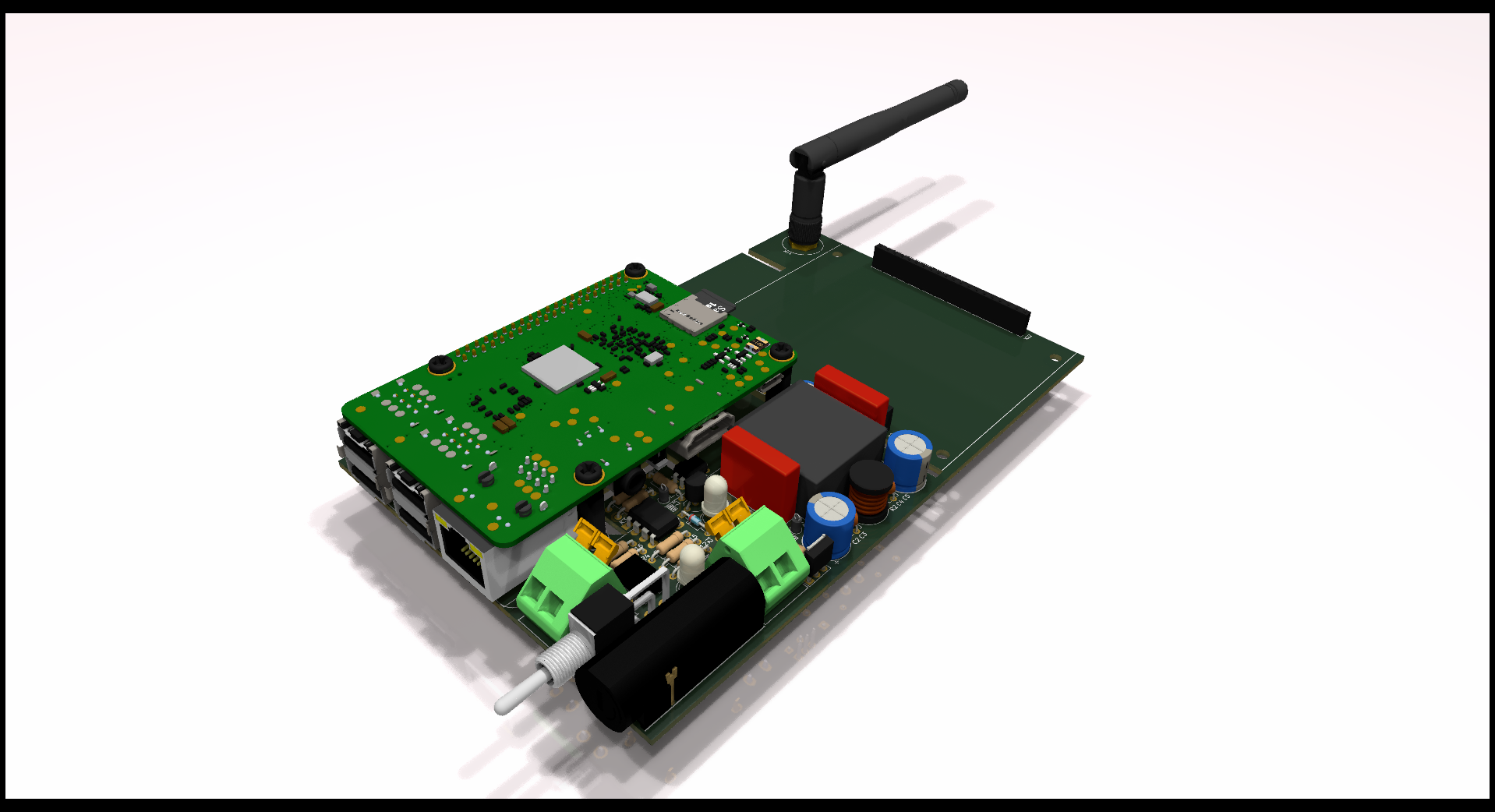
LoRa WindPower PCB
Power Supply
| Connector | Description |
|---|---|
| X3:1 | 24V |
| X3:2 | GND |
Signals
| Raspberry Pi | IC880A | External Signal | Description |
|---|---|---|---|
| K5:26 (GPIO7) | K6:13 | - | RESET |
| K5:23 (GPIO11) | K6:14 | - | SCLK |
| K5:21 (GPIO9) | K6:15 | - | MISO |
| K5:19 (GPIO10) | K6:16 | - | MOSI |
| K5:24 (GPIO8) | K6:17 | - | CS |
| K5:8 (GPIO14) | - | X10:2 | TXD (Serial Console); 3V3 |
| K5:10 (GPIO15) | - | X10:3 | RXD (Serial Console); 3V3 |
| K5:19 (GPIO10) | - | X8:1 | Shutdown Signal; 24V |
Note: check Schematic-Design for more Informations
Watteco IN'O
Power Supply
| Connector | Description |
|---|---|
| EXT_POWER+ | 24V (CLASS-C Device only) |
| EXT_POWER- | GND (CLASS-C Device only) |
Signals
| Connector | Description |
|---|---|
| OUT1+ | Output Relay for Shutdown |
| OUT1- | Output Relay for Shutdown |
Note: check Quick-Start-Guide and https://support.nke-watteco.com/ino-2/ for more Informations
Setup Raspberry Pi and IC880A as a Gateway
Follow Instructions on The Things Stack
https://www.thethingsindustries.com/docs/gateways/models/raspberry-pi/
Add Watteco Device to TTN
Follow Instructions on Watteco
https://support.watteco.com/ttnv3-tutorial/
Modify Files
Raspberry Pi Configuration
Add the following lines to the /boot/config.txt to activate SPI only for CS1 on SPI0:
dtparam=spi=on
dtoverlay=spi0-1cs,cs0_pin=8
Change Reset Pin Number
In various files the reset pin has to be changed according to the reset wiring (GPIO 7).
In /opt/ttn-station/bin/start.sh:
SX1301_RESET_BCM_PIN=7
Then add the following lines:
"radio_init": "/home/support/basicstation/deps/lgw/platform-rpi/reset_lgw.sh start 7",
"RADIO_INIT_WAIT": "2s"
to the file opt/ttn-station/config/station.conf in section station_conf. This section should look like below after changing:
"station_conf": {
    "routerid": "dca632fffe296b69",
    "log_file": "stderr",
    "log_level": "DEBUG", /* XDEBUG,DEBUG,VERBOSE,INFO,NOTICE,WARNING,ERROR,CRITICAL */
    "log_size": 10000000,
    "log_rotate": 3,
    "CUPS_RESYNC_INTV": "1s",
    "radio_init": "/home/support/basicstation/deps/lgw/platform-rpi/reset_lgw.sh start 7",
    "RADIO_INIT_WAIT": "2s"
}
LoRaWAN - MQTT Handler
To receive and send LoRaWAN messages, the MQTT integration of TTN is used. The python-script lora_mqtt.py in folder Source is handling the LoRa payload via MQTT. This script configures all LoRa devices within a LoRa application. All devices are configured to send periodically report messages (uplink) about the state of the relay output. If an external shutdown command is registered by the Raspberry Pi GPIO, a command (downlink) is send to trigger the relay output of the watteco device.
The script provide in this state no checking algorithm, that a downlink message was correctly received and executed by the device (no Acknolagement).
Note: More informations about the MQTT integration, visit https://www.thethingsindustries.com/docs/integrations/mqtt/
Note: More informations about controlling digital ouputs (payload), visit https://support.nke-watteco.com/onoff-cluster/
The script can be autostarted by using systemd, e.g. lora_mqtt.service. Adjust the path to the python script.
[Unit]
Description=LoRa-MQTT Handler
After=network.target ttn-station.service

[Service]
WorkingDirectory=/home/support/lora_mqtt
ExecStart=/home/support/lora_mqtt/lora_mqtt.py
SyslogIdentifier=lora_mqtt
Restart=on-failure
RestartSec=5

[Install]
WantedBy=multi-user.target
Copy the systemd service file to /lib/systemd/system/ and enable it:
sudo systemctl enable lora_mqtt.service
sudo systemctl start lora_mqtt.service
Timing Problems with Class A Devices
For testing, a Watteco IN'O Class A device was used. Since a Class A device can only receive a downlink message for a certain time (few seconds) after sending an uplink message, the min/max reporting time for the relay output was set to 60s/120s, to reduce the timespan for sending a downlink messages. Depending on the Spreading Factor (SF), this may result in a violation of the max airtime for a LoRa device per day. Without a reporting message being set, a Class A device will only send one void message per day, so only one time per day, a downlink message can be received by the device. So for production use case, a Class C device is recommended and the reporting time must be increased to achieve the specs of LoRa/TTN in termes of max airtime. Class C device has the advantage, that it can continuously receive a downlink message, because it is not battery driven and doesn't need to be set into sleep to increase battery lifetime.
It is a good practice to precalculate the airtime per message, depending on SF, bandwidth and the amount of bytes per message. With the result, the correct reporting time can be set.
Use the calculator provided by TTN:
https://www.thethingsnetwork.org/airtime-calculator
Additional Informations:
https://www.thethingsnetwork.org/docs/lorawan/duty-cycle/
https://www.thethingsnetwork.org/docs/lorawan/spreading-factors/
Definition Class A (Sleeping Devices): Downlink frames can only be transmitted after an uplink transmission by the sensor. Once the sensor sends an uplink frame, the end-device will open two receiving windows: RX1 and RX2, the network can then send on one of these windows a frame that will be taken into account by the sensor. When a sleeping device is not transmitting a frame it goes into a sleep mode where it does not listen to the network. This mode permits to reduce a lot the consumption of the sensor.
Definition Class C (Awake Devices): The network can send at any time a frame; it will be received by the sensor. The device open receive windows continuously.