ℹ Introduction
Welcome to the Wiki of the Xcom-API. This project is about an API (**A**pplication **P**rogramming **I**nterface) designed as a python-class, which is used to encode and decode byte-frames for communication between a Xtender-System and a PC, especially a Raspberry Pi with a Raspicomm extension module. The class also contains methods for error and frame-flag decoding and methods to get object or class informations. >**Note:** The API and the Test-Program was created with Microsoft's integrated development environment (IDE) Visual Studio Code (VSC). This is an Open-Source IDE from Microsoft for many different programming-languages for Windows, Linux and Mac with an easy to use git integration. So you can easily add this project to VSC by cloning this Git-Repository. Of course you can open the python-files with other IDE's you prefer too. > >####☁ Git-Repository-Link: https://gogs.es-lab.de/mueller_to/Xcom-API
On the following pages you will find many informations about the usage of the API such like: An explanation of the methods of the API and how to invoke these methods inside a python-script. Furthermore there are test-programs called "Xcom-Test-Program" and "Xcom-Test-Loop-Program", which you can use for testing the Xcom-API and where you get some impressions of how to use the Xcom-API. There are also explanation for how to use these test-programs. This concerns the hardware and software setup of the Raspberry Pi, if you won't use the given Raspberry Pi image.
##
:\\\Lib\site-packages
```
for example:
```text
C:\Program Files\Python34-64\Lib\site-packages
```
or under Linux the path:
```text
/usr/local/lib/
```
for example:
```text
/usr/local/lib/python3.4
```
To import the class use the python-code:
```python
>>> # import module
>>> from Xcom_API import Xcom_API
```
or:
```python
>>> # import module
>>> from Xcom_API import *
```
##### Create an Object:
Now you are able to create an object of the Xcom-API-Class. For example with the code:
```python
>>> # create object of the Xcom-API-Class
>>> object = Xcom_API()
```
If you create an object, the "*\_\_init\_\_*" method of the class will be called. It checks the passed arguments and store them. There are predefined arguments for this object, if you generate an objects without the relevant arguments, such like in the shown code-example before. The predefined arguments are:
```python
crc = True
source = 1
destination = 101
```
The "*crc*" value indicates, whether the CRC check for this object in active or not. The "*source*" value indicates the address of the Xcom-232i, which is the CAN-RS232-Bridge. Normally the standard address is "*1*", if you have only one Xcom-232i in your configuration. The "*destination*" value is the address of the Xtender-Module, which you want to communicate with. If you want to change one or more of these arguments, then change it's value. For example:
```python
>>> # create object of the Xcom-API-Class with CRC-Check disable and
>>> # destination address = 103
>>> object = Xcom_API(crc=False,destination=103)
```
For each Xtender-Module you want to communicate with, you must create an own object for it. You can't change any arguments after creating an object. This is a safety aspect, which prevents you against confusing code, because each object represents a Xtender-Module. So make sure, that the object name is well chosen.
##### Delete an Object:
To delete an object, just use the "*del*" expression.
```python
>>> # delete an object
>>> del object
```
This calls the "\_\_del\_\_" method of the class, which delete the object specific arguments such like: "crc", "sourc
### Class-Attributes
Class-Attributes are protected values, which are marked through an underscore "_" at the beginning of the Attribute name. Protected means, that these attributes can be read out und used as an input parameter for methods, but their value must not be changed. Otherwise the Xcom-API-Class will not work correctly.
You can use/read out an attribute with the command:
```python
>>> Xcom_API.
```
for example:
```python
>>> # Read out the number of an Info-Object_ID
>>> Xcom_API._info_battery_voltage
3000
```
##### Object_Type
```python
_object_type_info = 1
_object_type_parameter = 2
_object_type_message = 3
_object_type_datalog_field = 5
_object_type_datalog_transfer = 257
```
##### Info-Object_ID
```python
_info_battery_voltage = 3000
_info_battery_temperature = 3001
_info_battery_charge_current = 3005
_info_battery_voltage_ripple = 3006
_info_state_of_charge = 3007
_info_number_of_battery_elements = 3050
_info_input_voltage = 3011
_info_input_current = 3012
_info_input_frequency = 3084
_info_input_power = 3138
_info_output_voltage = 3021
_info_output_current = 3022
_info_output_frequency = 3085
_info_output_power = 3139
_info_operating_state = 3028
_info_boost_active = 3019
_info_state_of_inverter = 3049
_info_state_of_transfer_relay = 3020
_info_state_of_output_relay = 3030
_info_state_of_aux_relay_1 = 3031
_info_state_of_aux_relay_2 = 3032
_info_state_of_ground_relay = 3074
_info_state_of_neutral_transfer_relay = 3075
_info_state_of_remote_entry = 3086
```
##### Parameter-Object_ID
```python
_para_maximum_current_of_ac_source = 1107
_para_battery_charge_current = 1138
_para_smart_boost_allowed = 1126
_para_inverter_allowed = 1124
_para_type_of_detection_of_grid_loss = 1552
_para_charger_allowed = 1125
_para_charger_uses_only_power_from_ac = 1646
_para_ac_output_voltage = 1286
_para_inverter_frequency = 1112
_para_transfer_relay_allowed = 1128
_para_limitation_of_the_power_boost = 1607
_para_remote_entry_active = 1545
```
##### Property_ID
```python
_property_id_value = 1
_property_id_string = 1
_property_id_value_qsp = 5
_property_id_min_qsp = 6
_property_id_max_qsp = 7
_property_id_level_qsp = 8
_property_id_unsaved_value_qsp = 13
_property_id_invalid_Action = 0
_property_id_sd_start = 21
_property_id_sd_datablock = 22
_property_id_sd_ack_continue = 23
_property_id_sd_nack_retry = 24
_property_id_sd_abort = 25
_property_id_sd_finish = 26
```
##### Format
```python
_format_bool = [1,1]
_format_format = [2,2]
_format_short_int = [3,2]
_format_enum = [4,2]
_format_short_enum = [5,2]
_format_long_enum = [6,4]
_format_error = [7,2]
_format_int32 = [8,4]
_format_float = [9,4]
_format_byte = [10,1]
```
### Information-Methods
The information methods provide the user with the opportunity to inform about the current object properties and class information. The following methods can be used:
* [get_source_address](#get_source_address)
* [get_destination_address](#get_destination_address)
* [is_crc_check_active](#is_crc_check_active)
* [get_object_counter](#get_object_counter)
* [get_prog_name](#get_prog_name)
* [get_prog_version](#get_prog_version)
🗃 Xcom-API-Class
This class is used to encode byte-frames, which are needed to communicate with Xtender-Modules over the RS232-BUS with the help of the Xcom-232i. After encoding the byte-frame, you can use the module "pyserial" to communicate with the Serial-BUS and to put the byte-frame into the write-method of "pyserial". You can also decode read-frames of the Serial-BUS with this class. The class contains methods to generate read- or write-frames, and methods to decode frames. There are pre-defined types, properties and formats for the most important parameter- and information-numbers. This reduces the effort for generating byte-frames, but there are extended methods to encode byte-frames with other parameter- and information-numbers too, that you can find in the documentation of the Xcom-232i. The class also contains methods for error and frame-flag decoding and methods to get object or class informations >**Note:** The link to the documentation of the Xcom-232i can you find under the section: [Hardware Information](#hardware-information). On the following sections, there will be describe the [Information-Methods](#information-methods), [Public-Class-Methods](#public-class-methods), [Class-Attributes](#class-attributes) and how to [create and delete an object](#create-and-delete-an-object). ### Create and Delete an Object ##### Import Xcom-API-Class: To use the Xcom-API, either you need to import the class into your python-script, or you write your code directly inside the "*Xcom_API.py*" file. If you want to import the "*Xcom_API.py*" into your own python script, make sure, that the "*Xcom_API.py*" file is located inside the python-module search path. This is either the folder/directory where your script is located or under Microsoft Windows the path: ```text
#### get_source_address
##### Definition
```python
def get_source_address(self):
```
##### Description
The "*get_source_address*" method is used to check the source address of an object. It returns an integer value with it's source address.
##### Arguments
The "*self*" argument is pointing to the object, which calls the method.
##### Return Value
Type -> integer
##### Example Code
```python
>>> # create an object of the Xcom-API-Class
>>> Object = Xcom_API()
>>>
>>> # call the Method 'get_source_address'
>>> Src_Addr = Object.get_source_address()
>>>
>>> # print Src_Addr
>>> print(Src_Addr)
1
```
#### get_destination_address
##### Definition
```python
def get_destination_address(self):
```
##### Description
The "*get_destination_address*" method is used to check the destination address of an object. It returns an integer value with it's destination address.
##### Arguments
The "*self*" argument is pointing to the object, which calls the method.
##### Return Value
Type -> integer
##### Example Code
```python
>>> # create an object of the Xcom-API-Class
>>> Object = Xcom_API()
>>>
>>> # call the Method 'get_destination_address'
>>> Dest_Addr = Object.get_destination_address()
>>>
>>> # print Dest_Addr
>>> print(Dest_Addr)
101
```
#### is_crc_check_active
##### Definition
```python
def is_crc_check_active(self):
```
##### Description
The "*is_crc_check_active*" method is used to check whether the CRC-Check is activated or not. It returns a boolean value with the status of the CRC-Check. If CRC-Check is "*False*", the [get_data_from_frame](#get_data_from_frame), [get_data_from_frame_ext](#get_data_from_frame_ext) and [get_bin_from_frame_flags](#get_bin_from_frame_flags) methods will not do an CRC-Check before the frame will be decoded.
##### Arguments
The "*self*" argument is pointing to the object, which calls the method.
##### Return Value
Type -> boolean
##### Example Code
```python
>>> # create an object of the Xcom-API-Class
>>> Object = Xcom_API()
>>>
>>> # call the Method 'is_crc_check_active'
>>> CRC_Active = Object.is_crc_check_active()
>>>
>>> # print CRC_Active
>>> print(CRC_Active)
True
```
#### get_object_counter
##### Definition
```python
def get_object_counter():
```
##### Description
The "*get_object_counter*" method is used to check the number of objects. It returns an integer value of the counter. This method can be called with and without a created object.
##### Arguments
None
##### Return Value
Type -> integer
##### Example Code
```python
>>> # call the Method 'get_object_counter'
>>> Obj_Count = Xcom_API.get_object_counter()
>>>
>>> # print Obj_Count
>>> print(Obj_Count)
0
>>>
>>> # create an object of the Xcom-API-Class
>>> Object1 = Xcom_API(destination=102)
>>>
>>> # call the Method 'get_object_counter'
>>> Obj_Count = Object1.get_object_counter()
>>>
>>> # print Obj_Count
>>> print(Obj_Count)
1
>>>
>>> # create another object of the Xcom-API-Class
>>> Object2 = Xcom_API(destination=103)
>>>
>>> # call the Method 'get_object_counter'
>>> Obj_Count = Xcom_API.get_object_counter()
>>>
>>> # print Obj_Count
>>> print(Obj_Count)
2
>>>
>>> # delete objects
>>> del Object1
>>> del Object2
>>>
>>> # call the Method 'get_object_counter'
>>> Obj_Count = Xcom_API.get_object_counter()
>>>
>>> # print Obj_Count
>>> print(Obj_Count)
0
```
#### get_prog_name
##### Definition
```python
def get_prog_name():
```
##### Description
The "*get_prog_name*" method is used to return the API name. This method can be called with and without a created object.
##### Arguments
None
##### Return Value
Type -> string
##### Example Code
```python
>>> # call the Method 'get_prog_name'
>>> Obj_Name = Xcom_API.get_prog_name()
>>>
>>> # print Obj_Name
>>> print(Obj_Name)
'Xcom_API'
>>>
>>> # create an object of the Xcom-API-Class
>>> Object = Xcom_API()
>>>
>>> # call the Method 'get_prog_name'
>>> Obj_Name = Object.get_prog_name()
>>>
>>> # print Obj_Name
>>> print(Obj_Name)
'Xcom_API'
```
#### get_prog_version
##### Definition
```python
def get_prog_version():
```
##### Description
The "*get_prog_version*" method is used to return the version of the API. This method can be called with and without a created object.
##### Arguments
None
##### Return Value
Type -> string
##### Example Code
```python
>>> # call the Method 'get_prog_version
>>> Obj_Version = Xcom_API.get_prog_version()
>>>
>>> # print Obj_Version
>>> print(Obj_Version)
'v1.0'
>>>
>>> # create an object of the Xcom-API-Class
>>> Object = Xcom_API()
>>>
>>> # call the Method 'get_prog_version'
>>> Obj_Version = Object.get_prog_version()
>>>
>>> # print Obj_Version
>>> print(Obj_Version)
'v1.0'
```
### Public-Class-Methods
The Public-Class-Methods are used to encode and decode byte-frames. There are also Private-Class-Methods of the API, but they are only used inside the API for internal instructions and they are not available for the user. So the Private-Class-Methods will not be further described. The Public-Class-Methods are:
* [get_read_frame](#get_read_frame)
* [get_read_frame_ext](#get_read_frame_ext)
* [get_write_frame](#get_write_frame)
* [get_write_frame_ext](#get_write_frame_ext)
* [get_data_from_frame](#get_data_from_frame)
* [get_data_from_frame_ext](#get_data_from_frame_ext)
* [get_bin_from_frame_flags](#get_bin_from_frame_flags)
* [get_text_from_frame_flags](#get_text_from_frame_flags)
* [get_text_from_error_id](#get_text_from_error_id)
There are Methods either to encode 'read' or 'write' byte-frames and there are Methods to decode byte-frames. Furthermore there are also Methods to decode frame-flags and error-id as well.
The non extended methods, these are methods without an '_ext' expression inside the method names, can only be used with a known Object_ID, which are listed in the section [Class-Attributes](#class-attributes). These known Object_IDs contains info and parameter numbers, which are often used. So you can easily encode and decode byte-frames without the need to know of the background informations of the byte-frame structure.
If you want to encode and decode byte-frames with other Object-IDs, you must used the extended methods. To use these Methods, you need background informations of the byte-frame structure, wich are well explained in the technical documentation of the Xcom-232i. Otherwise the Xtender-System will possibly not understand the byte-frame and will send you an error.
>**Note:** The link to the documentation of the Xcom-232i can you find under the section: [Hardware Information](#hardware-information).
#### get_read_frame
##### Definition
```python
def get_read_frame(self, object_id):
```
##### Description
The "*get_read_frame*" method is used to encode a byte-frame for a 'read'-instruction. It can only be used with a known Object_ID, otherwise it will raise a Value_Error. It returns a bytearray of the frame.
##### Arguments
The "*self*" argument is pointing to the object, which calls the method.
The "*object_id*" is an info or parameter number, which you want to read out.
Info-Object_ID:
```python
_info_battery_voltage = 3000
_info_battery_temperature = 3001
_info_battery_charge_current = 3005
_info_battery_voltage_ripple = 3006
_info_state_of_charge = 3007
_info_number_of_battery_elements = 3050
_info_input_voltage = 3011
_info_input_current = 3012
_info_input_frequency = 3084
_info_input_power = 3138
_info_output_voltage = 3021
_info_output_current = 3022
_info_output_frequency = 3085
_info_output_power = 3139
_info_operating_state = 3028
_info_boost_active = 3019
_info_state_of_inverter = 3049
_info_state_of_transfer_relay = 3020
_info_state_of_output_relay = 3030
_info_state_of_aux_relay_1 = 3031
_info_state_of_aux_relay_2 = 3032
_info_state_of_ground_relay = 3074
_info_state_of_neutral_transfer_relay = 3075
_info_state_of_remote_entry = 3086
```
Parameter-Object_ID:
```python
_para_maximum_current_of_ac_source = 1107
_para_battery_charge_current = 1138
_para_smart_boost_allowed = 1126
_para_inverter_allowed = 1124
_para_type_of_detection_of_grid_loss = 1552
_para_charger_allowed = 1125
_para_charger_uses_only_power_from_ac = 1646
_para_ac_output_voltage = 1286
_para_inverter_frequency = 1112
_para_transfer_relay_allowed = 1128
_para_limitation_of_the_power_boost = 1607
_para_remote_entry_active = 1545
```
##### Return Value
Type -> bytearray
##### Example Code
```python
>>> # create an object of the Xcom-API-Class
>>> Object = Xcom_API()
>>>
>>> # call the Method 'get_read_frame'
>>> Byte_Frame = Object.get_read_frame(Xcom_API._info_battery_voltage)
>>>
>>> # print Byte_Frame
>>> print(Byte_Frame)
bytearray(b'\\xAA\\x00\\x01\\x00\\x00\\x00\\x65\\x00\\x00\\x00\\x0A\\x00\\x6F\\x71\\x00\\x01\\x01\\x00\\xB8\\x0B\\x00\\x00\\x01\\x00\\xC5\\x90')
```
#### get_read_frame_ext
##### Definition
```python
def get_read_frame_ext(self, object_type, object_id, property_id):
```
##### Description
The "*get_read_frame_ext*" method is used to encode a byte-frame for a 'read'-instruction with other Object_IDs listed in the technical documentation of the Xcom-232i. It returns a bytearray of the frame.
>**Note:** The link to the documentation of the Xcom-232i can you find under the section: [Hardware Information](#hardware-information).
##### Arguments
The "*self*" argument is pointing to the object, which calls the method.
The "*object_type*" indicates the type of the "*object_id*", whether it is for example an info or a parameter number.
Object_Type:
```python
_object_type_info = 1
_object_type_parameter = 2
_object_type_message = 3
_object_type_datalog_field = 5
_object_type_datalog_transfer = 257
```
The "*object_id*" is an info or parameter number, which you want to read out.
The "*property_id*" identifies the property of the data, which should be read out.
Property_ID:
```python
_property_id_value = 1
_property_id_string = 1
_property_id_value_qsp = 5
_property_id_min_qsp = 6
_property_id_max_qsp = 7
_property_id_level_qsp = 8
_property_id_unsaved_value_qsp = 13
_property_id_invalid_Action = 0
_property_id_sd_start = 21
_property_id_sd_datablock = 22
_property_id_sd_ack_continue = 23
_property_id_sd_nack_retry = 24
_property_id_sd_abort = 25
_property_id_sd_finish = 26
```
##### Return Value
Type -> bytearray
##### Example Code
```python
>>> # create an object of the Xcom-API-Class
>>> Object = Xcom_API()
>>>
>>> # set an Object_ID, which should be read out
>>> input_current = 3116
>>>
>>> # call the Method 'get_read_frame_ext'
>>> Byte_Frame = Object.get_read_frame_ext(Xcom_API._object_type_info, input_current, Xcom_API._property_id_value)
>>>
>>> # print Byte_Frame
>>> print(Byte_Frame)
bytearray(b'\\xAA\\x00\\x01\\x00\\x00\\x00\\x65\\x00\\x00\\x00\\x0A\\x00\\x6F\\x71\\x00\\x01\\x01\\x00\\x2C\\x0C\\x00\\x00\\x01\\x00\\x3A\\x4D')
```
#### get_write_frame
##### Definition
```python
def get_write_frame(self, object_id, property_data):
```
##### Description
The "*get_write_frame*" method is used to encode a byte-frame for a 'write'-instruction. It can only be used with a known Object_ID, otherwise it will raise a Value_Error. It returns a bytearray of the frame.
##### Arguments
The "*self*" argument is pointing to the object, which calls the method.
The "*object_id*" is a parameter number, whose value you want to change.
Parameter-Object_ID:
```python
_para_maximum_current_of_ac_source = 1107
_para_battery_charge_current = 1138
_para_smart_boost_allowed = 1126
_para_inverter_allowed = 1124
_para_type_of_detection_of_grid_loss = 1552
_para_charger_allowed = 1125
_para_charger_uses_only_power_from_ac = 1646
_para_ac_output_voltage = 1286
_para_inverter_frequency = 1112
_para_transfer_relay_allowed = 1128
_para_limitation_of_the_power_boost = 1607
_para_remote_entry_active = 1545
```
The "*property_data*" is the value, you want to send.
##### Return Value
Type -> bytearray
##### Example Code
```python
>>> # create an object of the Xcom-API-Class
>>> Object = Xcom_API()
>>>
>>> # create a variable with a value for the Property_Data
>>> Data_in_Ampere = 32.0
>>>
>>> # call the Method 'get_write_frame'
>>> Byte_Frame = Object.get_write_frame(Xcom_API._para_maximum_current_of_ac_source, Data_in_Ampere)
>>>
>>> # print Byte_Frame
>>> print(Byte_Frame)
bytearray(b'\\xAA\\x00\\x01\\x00\\x00\\x00\\x65\\x00\\x00\\x00\\x0E\\x00\\x73\\x79\\x00\\x02\\x02\\x00\\x53\\x04\\x00\\x00\\x05\\x00\\x00\\x00\\x00\\x42\\xA1\\xE6')
```
#### get_write_frame_ext
##### Definition
```python
def get_write_frame_ext(self, object_type, object_id, property_id, property_data, data_format):
```
##### Description
The "*get_write_frame_ext*" method is used to encode a byte-frame for a 'write'-instruction with other Object_IDs listed in the technical documentation of the Xcom-232i. It returns a bytearray of the frame.
>**Note:** The link to the documentation of the Xcom-232i can you find under the section: [Hardware Information](#hardware-information).
##### Arguments
The "*self*" argument is pointing to the object, which calls the method.
The "*object_type*" indicates the type of the "*object_id*", whether it is for example an info or a parameter number.
Object_Type:
```python
_object_type_info = 1
_object_type_parameter = 2
_object_type_message = 3
_object_type_datalog_field = 5
_object_type_datalog_transfer = 257
```
The "*object_id*" is a parameter number, whose value you want to change.
The "*property_id*" identifies the property of the data, which should be change.
Property_ID:
```python
_property_id_value = 1
_property_id_string = 1
_property_id_value_qsp = 5
_property_id_min_qsp = 6
_property_id_max_qsp = 7
_property_id_level_qsp = 8
_property_id_unsaved_value_qsp = 13
_property_id_invalid_Action = 0
_property_id_sd_start = 21
_property_id_sd_datablock = 22
_property_id_sd_ack_continue = 23
_property_id_sd_nack_retry = 24
_property_id_sd_abort = 25
_property_id_sd_finish = 26
```
The "*property_data*" is the value, you want to send.
The "*data_format*" described the format of the "*property_data*".
Format:
```python
_format_bool = [1,1]
_format_format = [2,2]
_format_short_int = [3,2]
_format_enum = [4,2]
_format_short_enum = [5,2]
_format_long_enum = [6,4]
_format_error = [7,2]
_format_int32 = [8,4]
_format_float = [9,4]
_format_byte = [10,1]
```
##### Return Value
Type -> bytearray
##### Example Code
```python
>>> # create an object of the Xcom-API-Class
>>> Object = Xcom_API()
>>>
>>> # set an Object_ID, whose value should be change
>>> Equalization_current = 1290
>>>
>>> # create a variable with a value for the Property_Data
>>> Data_in_Ampere = 120.0
>>>
>>> # call the Method 'get_write_frame_ext'
>>> Byte_Frame = Object.get_write_frame_ext(Xcom_API._object_type_parameter, Equalization_current, Xcom_API._property_id_value, Data_in_Ampere, Xcom_API._format_float)
>>>
>>> # print Byte_Frame
>>> print(Byte_Frame)
bytearray(b'\\xAA\\x00\\x01\\x00\\x00\\x00\\x65\\x00\\x00\\x00\\x0E\\x00\\x73\\x79\\x00\\x02\\x02\\x00\\x0A\\x05\\x00\\x00\\x01\\x00\\x00\\x00\\xF0\\x42\\x45\\xDD')
```
#### get_data_from_frame
##### Definition
```python
def get_data_from_frame(self, bytearray_of_frame):
```
##### Description
The "*get_data_from_frame*" method is used to decode data from the received byte-frame, what you get from the Xtender-System. If CRC-Check is active, it will check the byte-frame and raises a Value_Error, if a CRC-Error was detected. It can only be used with a known Object_ID, otherwise it will raise a Value-Error. This method return a list with two elements. The first is a boolean value, which is true, if the xtender-system detects an error and the second element of the list then contains the error-id. If no error occures, then the first element is false und the second element contains the answer of your request. The returned value of the second element is a string, integer or float, depending of the service (read/write) of the request frame and of the format of the received Property_Data.
##### Arguments
The "*self*" argument is pointing to the object, which calls the method.
The "*bytearray_of_frame*" argument is the frame what you get, when you receive data from the serial port.
##### Return Value
Type -> list
list[0]: Type -> boolean
list[1]: Type -> depending of the service (read/write) of the request frame and of the format of the received Property_Data
##### Example Code
```python
>>> # create an object of the Xcom-API-Class
>>> Object = Xcom_API()
>>>
>>> # create a variable with a received frame
>>> Frame = bytearray(b'\\xAA\\x37\\x65\\x00\\x00\\x00\\x01\\x00\\x00\\x00\\x0E\\x00\\xAA\\x66\\x02\\x01\\x01\\x00\\xB8\\x0B\\x00\\x00\\x01\\x00\\x00\\x40\\x42\\x42\\x8B\\x46')
>>>
>>> # call the Method 'get_data_from_frame'
>>> Answer = Object.get_data_from_frame(Frame)
>>>
>>> # print Answer
>>> print(Answer)
(False, 48.5625)
```
#### get_data_from_frame_ext
##### Definition
```python
def get_data_from_frame_ext(self, bytearray_of_frame, data_format):
```
##### Description
The "*get_data_from_frame_ext*" method is used to decode data from the received byte-frame, what you get from the Xtender-System. If CRC-Check is active, it will check the byte-frame and raises a Value_Error, if a CRC-Error was detected. This method return a list with two elements. The first is a boolean value, which is true, if the xtender-system detects an error and the second element of the list then contains the error-id. If no error occures, then the first element is false und the second element contains the answer of your request. The returned value of the second element is a string, integer or float, depending of the service (read/write) of the request frame and of the format of the received Property_Data.
##### Arguments
The "*self*" argument is pointing to the object, which calls the method.
The "*bytearray_of_frame*" argument is the frame what you get, when you receive data from the serial port.
The "*data_format*" described the format of the received Property_Data.
Format:
```python
_format_bool = [1,1]
_format_format = [2,2]
_format_short_int = [3,2]
_format_enum = [4,2]
_format_short_enum = [5,2]
_format_long_enum = [6,4]
_format_error = [7,2]
_format_int32 = [8,4]
_format_float = [9,4]
_format_byte = [10,1]
```
##### Return Value
Type -> list
list[0]: Type -> boolean
list[1]: Type -> depending of the service (read/write) of the request frame and of the format of the received Property_Data
##### Example Code
```python
>>> # create an object of the Xcom-API-Class
>>> Object = Xcom_API()
>>>
>>> # create a variable with a received frame
>>> Frame = bytearray(b'\\xAA\\x37\\x65\\x00\\x00\\x00\\x01\\x00\\x00\\x00\\x0E\\x00\\xAA\\x66\\x02\\x01\\x02\\x00\\x53\\x04\\x00\\x00\\x05\\x00\\x00\\xD0\\x14\\x42\\x86\\x8D')
>>>
>>> # call the Method 'get_data_from_frame_ext'
>>> Answer = Object.get_data_from_frame_ext(Frame, Xcom_API._format_float)
>>>
>>> # print Answer
>>> print(Answer)
(False, 37.203125)
```
#### get_bin_from_frame_flags
##### Definition
```python
def get_bin_from_frame_flags(self, bytearray_of_frame):
```
##### Description
The "*get_bin_from_frame_flags*" method is used to return the frame-flags as a binary. If CRC-Check is active, it will check the byte-frame and raises a Value_Error, if a CRC-Error was detected.
##### Arguments
The "*self*" argument is pointing to the object, which calls the method.
The "*bytearray_of_frame*" argument is the frame what you get, when you receive data from the serial port.
##### Return Value
Type -> string(binary)
##### Example Code
```python
>>> # create an object of the Xcom-API-Class
>>> Object = Xcom_API()
>>>
>>> # create a variable with a received frame
>>> Frame = bytearray(b'\\xAA\\x37\\x65\\x00\\x00\\x00\\x01\\x00\\x00\\x00\\x0E\\x00\\xAA\\x66\\x02\\x01\\x01\\x00\\xB8\\x0B\\x00\\x00\\x01\\x00\\x00\\x40\\x42\\x42\\x8B\\x46')
>>>
>>> # call the Method 'get_bin_from_frame_flags'
>>> Answer = Object.get_bin_from_frame_flags(Frame)
>>>
>>> # print Answer
>>> print(Answer)
'0b00110111'
```
#### get_text_from_frame_flags
##### Definition
```python
def get_text_from_frame_flags(self, bytearray_of_frame):
```
##### Description
The "*get_text_from_frame_flags*" method is used to return the frame-flags as a list with explanation (string) for each bit, starting with lsb. If CRC-Check is active, it will check the byte-frame and raises a Value_Error, if a CRC-Error was detected.
##### Arguments
The "*self*" argument is pointing to the object, which calls the method.
The "*bytearray_of_frame*" argument is the frame what you get, when you receive data from the serial port.
##### Return Value
Type -> list
list[0:5]: Type -> string
##### Example Code
```python
>>> # create an object of the Xcom-API-Class
>>> Object = Xcom_API()
>>>
>>> # create a variable with a received frame
>>> Frame = bytearray(b'\\xAA\\x37\\x65\\x00\\x00\\x00\\x01\\x00\\x00\\x00\\x0E\\x00\\xAA\\x66\\x02\\x01\\x01\\x00\\xB8\\x0B\\x00\\x00\\x01\\x00\\x00\\x40\\x42\\x42\\x8B\\x46')
>>>
>>> # call the Method 'get_text_from_frame_flags'
>>> Answer = Object.get_text_from_frame_flags(Frame)
>>>
>>> # print Answer
>>> print(Answer)
('Messages are pending.','A reset or restart was carried out.','The SD-Card is present.','The SD-Card is not full.','New datalog file on the SD-Card.','Datalogger is supported.')
```
#### get_text_from_error_id
##### Definition
```python
def get_text_from_error_id(self, error_id):
```
##### Description
The "*get_text_from_error_id*" method is used to get the error message from the "*error_id*".
##### Arguments
The "*self*" argument is pointing to the object, which calls the method.
The "*error_id*" argument is an integer value send from the Xtender-system.
##### Return Value
Type -> string
##### Example Code
```python
>>> # create an object of the Xcom-API-Class
>>> Object = Xcom_API()
>>>
>>> # create a variable with an Error_ID
>>> Error_ID = 0x0022
>>>
>>> # call the Method 'get_text_from_error_id'
>>> Answer = Object.get_text_from_error_id(Error_ID)
>>>
>>> # print Answer
>>> print(Answer)
'OBJECT_ID_NOT_FOUND'
```
##
 The Raspberry Pi is used to execute the test-program and with the help of the RaspiComm module is a RS232 connection to the Xcom-232i ensue. The Xcom-232i is a bridge betwenn the RS232 serial-Bus and the CAN-BUS, which handles the communication between the Xtender-System.
In the following sections you will get hardware-information and setup descriptions for the Raspberry Pi and the Xcom-232i.
### Hardware Information
The following table shows the needed hardware components and their usage and give you links to the product information and documentation. These components are necessary if you want to use the Xcom-Test-Program and Xcom-Test-Loop-Program.
| Component | Function | Product Information | Documentation |
|:----|:----|:----:|:----:|
| Raspberry Pi 3 | single board computer, on which is running the program | [
The Raspberry Pi is used to execute the test-program and with the help of the RaspiComm module is a RS232 connection to the Xcom-232i ensue. The Xcom-232i is a bridge betwenn the RS232 serial-Bus and the CAN-BUS, which handles the communication between the Xtender-System.
In the following sections you will get hardware-information and setup descriptions for the Raspberry Pi and the Xcom-232i.
### Hardware Information
The following table shows the needed hardware components and their usage and give you links to the product information and documentation. These components are necessary if you want to use the Xcom-Test-Program and Xcom-Test-Loop-Program.
| Component | Function | Product Information | Documentation |
|:----|:----|:----:|:----:|
| Raspberry Pi 3 | single board computer, on which is running the program | [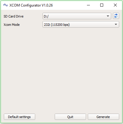
```
If "*unzip*" is not installed, you can install it with the bash-command:
```bash
sudo apt-get install unzip
```
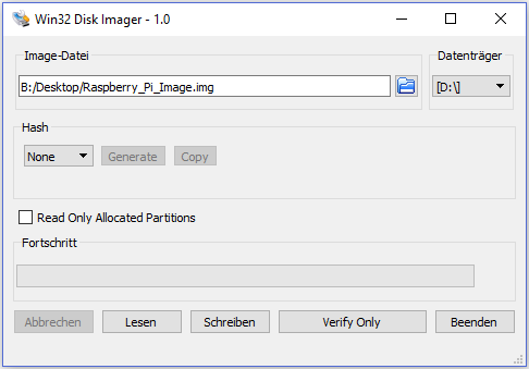
Copying the image-file to a SD-Card will be done with the ```dd``` command.
> **Note:** Use of the ```dd``` tool can overwrite any partition of your machine. If you specify the wrong device in the instructions below, you could delete your primary Linux partition. Please be careful.
* Insert a SD-Card into your computer with at least 8 GB storage capacity.
* Run the bash-command:
```
bash df -h
```
* The left column of the results from ```df -h``` command gives the device name of your SD card. It will be listed as something like ```/dev/mmcblk0p1``` or ```/dev/sdX1```, where "*X*" is a lower case letter indicating the device. The last part (p1 or 1 respectively) is the partition number. You want to write to the whole SD card, not just one partition. You therefore need to remove that section from the name. You should see something like ```/dev/mmcblk0``` or ```/dev/sdX``` as the device name for the whole SD card. Note that the SD card can show up more than once in the output of ```df```. It will do this if you have previously written a Raspberry Pi image to this SD card, because the Raspberry Pi SD images have more than one partition.
* Now you have noted the device name, you need to unmount it so that files can't be read or written to the SD card while you are copying over the SD image. So run the bash-command ```umount /dev/sdX1```, replacing ```sdX1``` with whatever your SD card's device name is, including the partition number. If your SD card shows up more than once in the output of ```df```, this shows that the card has multiple partitions. You should unmount all of these partitions.
* Now in a terminal window, write the image to the card with the command below, making sure you replace the input file ```if=``` argument with the path to your ```img``` file, and the ```/dev/sdX``` in the output file ```of=``` argument with the correct device name. This is very important, as you will lose all the data on the hard drive if you provide the wrong device name. Make sure the device name is the name of the whole SD card as described above, not just a partition. For example: ```sdd```, not ```sdds1``` or ```sddp1```, and ```mmcblk0```, not ```mmcblk0p1```.
```bash
dd bs=4M if=Raspberry_Pi_Image.img of=/dev/mmcblk0 conv=fsync
```
> **Note:** The block size set to ```4M``` will work most of the time. If not, try ```1M```, although this will take considerably longer. Also note that if you are not logged in as root you will need to prefix this with ```sudo```.
* After copying the image-file to the SD-Card, you can insert the SD-Card to your Raspberry Pi and boot it up [**[1](#references)**].
```
##### Activate PiGPIO-Daemon
The test-programs uses PiGPIO to access the GPIO pins. The PiGPIO module needs a daemon-process, which handles the communication between GPIOs and the module [**[5](#references)**]. You can start the daemon-process with:
```bash
sudo pigpiod
```
If you want to start the daemon-process with every bootup of the Raspberry pi, you need to open the ```rc.local```:
```bash
sudo nano /etc/rc.local
```
There you add a line with ```pigpiod``` before ```exit 0```. The file should be look like:
```bash
#!/bin/sh -e
#
# rc.local
#
# This script is executed at the end of each multiuser runlevel.
# Make sure that the script will "exit 0" on success or any other
# value on error.
#
# In order to enable or disable this script just change the execution
# bits.
#
# By default this script does nothing.
# Print the IP address
_IP=$(hostname -I) || true
if [ "$_IP" ]; then
printf "My IP address is %s\n" "$_IP"
fi
pigpiod
exit 0
```
##
```
You can start the test-program with the bash-command:
```bash
python3 .py
```
The "*\*" should be either "*Xcom_Test_Loop_Program*" or "*Xcom_Test_Program*". After starting one of these test-programs, it will start the program-setup and will ask you for some initialize parameters. These are:
* COM-Port (Normally: /dev/ttyAMA0)
* Baudrate (depends on your Xcom-232i setup)
* Destination-Address (Xtender-Module)
* Soure-Address (Normally your-Raspberry Pi: 1)
* CRC-Check (True/1 or False/0)
You can skip the program-setup by starting the test-program with the mentioned parameters. The sequence of the parameters must not be changed. For example:
```bash
python3 .py /dev/ttyAMA0 115200 101 1 True
```
If everything is ok, you are now inside the main menu of the test-program and you can follow the instructions, which are displayed.
### Xcom-Test-Loop-Program
The Xcom-Test-Loop-Program sends cyclical a request to a Xtender-System and display whose answer. After starting the Xcom-Test-Loop-Program and after finishing the program-setup, you need to enter an Object-ID, which is used to encode the request-frame with the method "*get_read_frame*". The Object_IDs are mentioned under section: [Class-Attributes](#class-attributes). Then the test-program sends the request and receive the answer over the serial connection. The answer will be decode with the method "*get_data_from_frame*" and displayed. The loop of the test-program run as fast as possible and is limited by the transfer speed of the serial connection and of the CAN-BUS load.
### Xcom-Test-Program
This program demonstrate the functionality of the Xcom_API-class. After starting the Xcom-Test-Program and after finishing the program-setup, you can either enter an Information-Method to test their functionallity or you enter a function, which demonstrate the functionallity of the Public-Class-Methods. The Xcom-Test-Program is user-friendly designed, so you only need to follow the displayed instructions.
>**Note:** If you want to use the function, which uses the extended Public-Class-Methods, you will need background informations of the byte-frame structure, which are well explained in the technical documentation of the Xcom-232i. Otherwise the Xtender-System or the program will not understand you and will display an error. The link to the documentation of the Xcom-232i can you find under the section: [Hardware Information](#hardware-information).
##
*Installing operating system images on Linux*
[https://www.raspberrypi.org/documentation/installation/installing-images/linux.md](https://www.raspberrypi.org/documentation/installation/installing-images/linux.md)
(20/08/2017) **[2]** Raspberry Pi
*Raspi-Config*
[https://www.raspberrypi.org/documentation/configuration/raspi-config.md](https://www.raspberrypi.org/documentation/configuration/raspi-config.md) (20/08/2017) **[3]** Hudson, G.
*Raspberry Pi 3 compatibility (BT disable & serial port remap fix)*
[https://openenergymonitor.org/forum-archive/node/12311.html](https://openenergymonitor.org/forum-archive/node/12311.html) (20/08/2017) **[4]** Raspberry Tips
*UART auf dem RaspberryPi nutzen*
[https://raspberry.tips/raspberrypi-einsteiger/uart-auf-dem-raspberrypi-nutzen/](https://raspberry.tips/raspberrypi-einsteiger/uart-auf-dem-raspberrypi-nutzen/) (20/08/2017) **[5]** PiGPIO
*PiGPIO Daemon*
[http://abyz.co.uk/rpi/pigpio/pigpiod.html](http://abyz.co.uk/rpi/pigpio/pigpiod.html) (20/08/2017) --- **Hochschule Anhalt | Anhalt University of Applied Sciences | Department 6 EMW
Xcom-API**
💻 Hardware Setup
This section explains the hardware configuration, which is necessary to use the test-programs. The test-programs were designed especially for using a Raspberry Pi with the RaspiComm module. Of course the Xcom-API-Class itself can be used in own programs with other distributions and plattforms, which can run python code. The chart below shows the connection of the hardware.🔗
](https://www.raspberrypi.org/products/raspberry-pi-3-model-b/) | [🔗
](https://www.raspberrypi.org/documentation/) | | RasPiComm | expansion board for the Raspberry Pi, which provides a RS232-Port over the GPIOs (UART) of the Raspberry Pi | Product is EOL | Product is EOL | | Xcom-232i | CAN to RS232 Bridge, which is used to communicate with the Xtender-Modules | [🔗
](https://www.studer-innotec.com/en/accessoires/xtender-series/communication-module-xcom-232i-770) | [🔗
](https://www.studer-innotec.com/media/document/0/studer-manuel-xcom-232i-v1.3.0_en.pdf) [🔗
](https://www.studer-innotec.com/media/document/0/technical-specification-xtender-serial-protocol-v1.6.24.zip) | | RCC-02 | remote control and programming unit for displaying the status informations and to program parameters of the Xtender-Modules | [🔗
](https://www.studer-innotec.com/en/accessoires/xtender-series/rcc-02-remote-control-and-programming-centre-767) | [🔗
](https://www.studer-innotec.com/media/document/0/manuel-rcc-v4.6.0_en.pdf) | | Xtender-Series| is used as Battery charger and as DC to AC converter and to supply electrical power | [🔗
](https://www.studer-innotec.com/en/products/xtender-series/) | [🔗
](https://www.studer-innotec.com/media/document/0/manuel-xtender-v4.7.0_en-1.pdf) ### Xcom-232i-Setup The Xcom-232i is a bridge for the RS232-BUS to the CAN-BUS. The test-programms for the Xcom-API-Class will ask you for the baudrate. So it is essential, that you know the baudrate of the Xcom-232i, otherwise the communication between the Raspberry Pi and the Xcom-232i will fails. The standard baudrate for the RS232-BUS is 38400, but you are able to change this value to 115200. To do that you need the Xcom-Configurator, which is only available for a windows operating system. > **Download-Link Xcom-Configurator:** [https://www.studer-innotec.com/media/document/0/xcomconfiguratorsetup_1.0.26.0.zip](https://www.studer-innotec.com/media/document/0/xcomconfiguratorsetup_1.0.26.0.zip) The picture below shows the Xcom-Configurator program.Login-informations:
Username: pi
Password: iotraspi
Login-informations:
Username: pi
Password: iotraspi
⁉ Test-Program
The test-programs demonstrate the functionality of the Xcom_API-class. To use these programs a Raspberry Pi with a Raspicomm extender module and a RS232-bridge called Xcom-232i is required. Make sure you have setup your Raspberry Pi correctly, just like explained in section [Hardware Setup](#hardware-setup) or you use the available Image-File of the Raspberry Pi, where everything is ready configured. There are two test-programs available: * [Xcom-Test-Loop-Program](#xcom-test-loop-program) * [Xcom-Test-Program](#xcom-test-program) In the following sections, there will be described these programs and explained how to run these programs. ### Run Test-Program To run the test-programs make sure, that the Xcom_API.py is inside the python search-path. More Informations about that can you find in section: [Create and Delete an Object](#create-and-delete-an-object). The test-programs needs the following python-modules: * ptvsd * serial (pyserial) * pigpio You can check, whether these modules are available with the bash-command: ```bash pip3 list ``` If one of these modules are missing, you can install it with the bash-command: ```bash pip3 install📚 References
**[1]** Raspberry Pi*Installing operating system images on Linux*
[https://www.raspberrypi.org/documentation/installation/installing-images/linux.md](https://www.raspberrypi.org/documentation/installation/installing-images/linux.md)
(20/08/2017) **[2]** Raspberry Pi
*Raspi-Config*
[https://www.raspberrypi.org/documentation/configuration/raspi-config.md](https://www.raspberrypi.org/documentation/configuration/raspi-config.md) (20/08/2017) **[3]** Hudson, G.
*Raspberry Pi 3 compatibility (BT disable & serial port remap fix)*
[https://openenergymonitor.org/forum-archive/node/12311.html](https://openenergymonitor.org/forum-archive/node/12311.html) (20/08/2017) **[4]** Raspberry Tips
*UART auf dem RaspberryPi nutzen*
[https://raspberry.tips/raspberrypi-einsteiger/uart-auf-dem-raspberrypi-nutzen/](https://raspberry.tips/raspberrypi-einsteiger/uart-auf-dem-raspberrypi-nutzen/) (20/08/2017) **[5]** PiGPIO
*PiGPIO Daemon*
[http://abyz.co.uk/rpi/pigpio/pigpiod.html](http://abyz.co.uk/rpi/pigpio/pigpiod.html) (20/08/2017) --- **Hochschule Anhalt | Anhalt University of Applied Sciences | Department 6 EMW
Xcom-API**
Tobias Müller, M. Eng.
📧 Tobias.Mueller@HS-Anhalt.de
© es-lab.de, 10.07.2018